Winstar OLED Display Library and Driver for Arduino
27 June, 2025
Library and Driver Github Repository: HERE
100x32 PNG to formated hexadecimal converter: HERE
A Beautiful Red OLED Caught my Eye
In January this year, I picked up a Winstar OLED display for $80 at an electronics shop in Osaka, drawn in by the amazing contrast and cool animation playing below, I had to buy it. Without knowledge of if I was being ripped off, or even if the display would be considered "worth using", my mind was filled with fun ideas for animations and artwork I could hopefully display on it. I didn't know what I was getting into as this was the first time I had tried to use a display, it definitely took a lot longer than expected but im glad it did as I learnt a lot and felt very satisfied by the end.
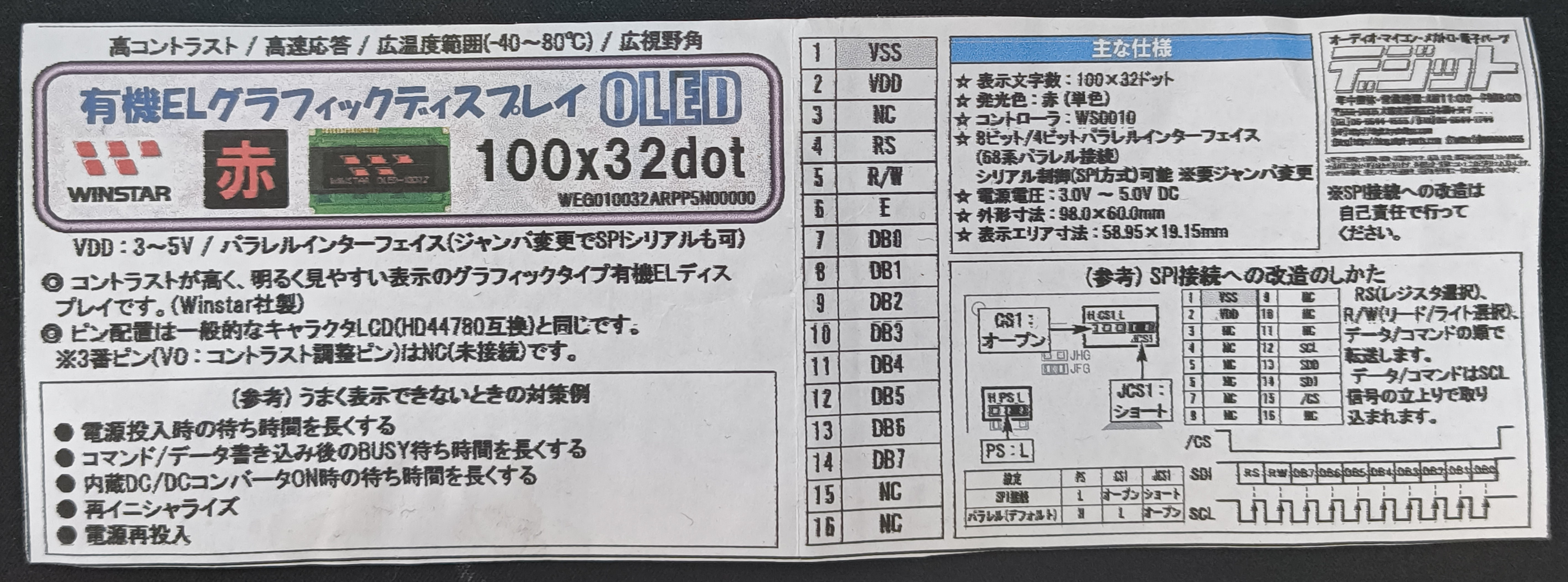
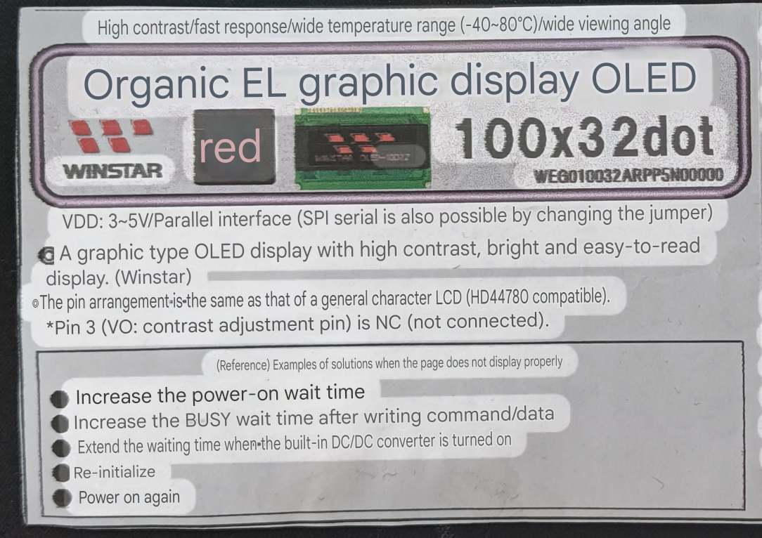
I assumed it would be a fairly simple plug-and-play device, as the information card it came with stated it used a similar interface to the common "HD44780" display controller, which apparently had a lot of support available.
I soon learned the importance of the display controller, I was under the impression that a similar-looking display (same pinout, resolution, even size) would all function in a similar way with a few small tweaks. After more research, I learned that my display used two WS0010 chips and all the libraries and drivers I could find were for single-chip displays (such as the Winstar 100x16 OLED) as well as being exclusively for character-mode, which allows you display characters from a saved font table on the display over two lines. I wanted to upload pixel art and create fun animations! Not display scrolling text.
To begin my project, I initially wanted to find: An example of someone using this display, someone's working initialisation code, or more detailed instructions on the initialisation process.
Lots of learning, but no progress
I visited many forums, GitHub repositories, around 10 versions of the chip, and display datasheet in multiple languages, Russian, Chinese, Japanese, and Finnish chatrooms, plus tried countless variations of the stated initialisation process on the datasheet, but was having no luck. I couldn't contact the shop I purchased it from either, all I could find was a fax address and an enquiry form for business support. Some useful information that I did manage to find is linked below:
Russian site with one of the largest versions of the datasheet.
Different Japanese store page with working graphical code for WEG010016 (100x16) graphical display.
There was an abundance (comparatively to mine) of code written for similar displays such as the Winstar WEG010016 (although again most was for character-mode, not graphical), this is a very similar display to mine but as previously mentioned only uses one controller chip compared to my two. I could not for the life of me figure out the correct sequence of commands to send data to one chip and then the other. Days and weeks of trial and error passed, changing delays between command calls, (apparently this is important for this display) and even questioning if the display even worked. Maybe it had been broken from when I had bought it? Maybe I had wired the pins incorrectly and blown something? I was receiving no feedback from the display besides from multimeter measurements which to be honest I didn't exactly know the meaning of, at least I was getting a reading.
Sample code from Winstar!
I send an email to Winstar asking if they knew anything about this display, and if they had any sample code laying around. A few weeks later I received the requested code along with a message asking me where I got my display from, why I chose the colour red (apparently no one ever bought it), and to please consider upgrading to a supported product. There is a QC sticker dated for 2015 on the back of the PCB, this display has been EOL for a while now.
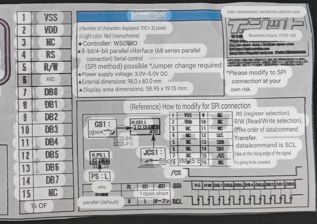
Note: If anyone ever buys this display, the small information card I received with it states that pin 15 and pin 16 (chip select 1 and chip select 2) are NC or Not Connected but they definitely are and are needed for the display to work. Before I discovered this, I assumed I would never get the display working unless I figured out how to connect these pins on the PCB, which are crucial for selecting and communicating with each of the two WS0010 chips independently.
The sample code Winstar sent was written in 2010 for an Intel 8051 8-bit microcontroller, so I now had the task of porting it over to C++ so it would run on my Arduino Uno. Once again this required more learning and research as concepts such as writing directly to the P1 Data bus (a specific input/output port on the 8051), sbits (single bit-addressable memory locations), and _nop_(); (a "no operation" instruction used for timing) were very unfamiliar to me.
Learning about the NOP instruction was interesting, from what I researched, a NOP or "No Operation" instruction tells the processor to do nothing for one machine cycle, this can be used for a variety of purposes but in this case is used as a delay similar to Arduino's delay() function. A NOP takes a different amount of time for each processor as it's dictated by the clock speed and number of clock cycles per machine cycle. In the instance of the Intel 8051 the _nop_() function creates a 1 microsecond delay, as a standard 8051 runs at 12MHz, and requires 12 clock cycles to complete a full machine cycle (num of clock cycles/clock speed = 12/12000000Hz). For my Arduino, using the delayMicroseconds() function should be a perfect substitute!
How to Display an image
The original code also held a frame in a [4][100] 2D array. Each index stored an 8-bit hexadecimal value, where each bit within that byte corresponded to an individual pixel. A '1' in a bit position would switch the corresponding pixel on, while a '0' would leave it off, effectively using bitmasking to represent 8 vertical pixels per byte. I kept this same design in my code, along with keeping the same logic for drawing the frame on the screen. On that note I could now figure out how this was possible. The datasheet has a diagram that shows how each pixel is addressed but too be honest it went a bit over my head initially, following along the demo code it becomes very clear and straightforward.
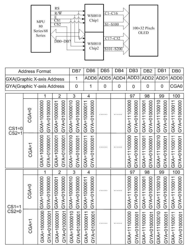
Here we can see two distinct boxes representing each chip, to send data to the first chip (CS1), we initially need to send a instruction turning CS2 to HIGH and CS1 to LOW, remembering that LOW enables and HIGH disables. We define SET_DDRAM_ADDR to 0x80 as this corresponds to the value of GXA at the beginning of each row. We can see that the Graphic Y-Axis Address can only be two states, either 0x40 or 0x41 depending on the value of data pin DB0, these values are defined as SET_Y_ADDR_0 and SET_Y_ADDR_1 respectively. Now all that's left is to read from our picture array stored in program memory, after each write, the display's Cursor is incremented by one on the X-Axis, this is why we must write the instruction SET_DDRAM_ADDR before beginning to write to the next line.
Below is a code snippet of the showPic function I wrote, the full code is in the Github link at the top of the page. It shows how each chip is selected one at a time, with the first chip writing from [0][0] to [0][99] and then [1][0] to [1][99], resetting the X-Axis address and then changing the Y-Axis address before entering each loop, the same happens when we swap to chip 2. I would not have been able to figure this out if it wasn't for the sample Winstar sent me, I don't want to post it here without their permission, but send me a message if you would like to see the original.
Showing an Image
    void WS0010_Display::showPic(const unsigned char pic_data[][100], unsigned char size)
    {
        unsigned char i;
        byte data_byte;

        // Chip 1
        // Disable chip 2 and enable chip 1
        digitalWrite(_cs2_pin, HIGH);
        digitalWrite(_cs1_pin, LOW);

        // First line
        // Set DDRAM address to 0 (base) and Y address to 0
        _writeCommand(SET_DDRAM_ADDR);
        _writeCommand(SET_Y_ADDR_0);
        for (i = 0; i < size; i++) {
            data_byte = pgm_read_byte(&pic_data[0][i]);
            _writeData(data_byte);
        }

        // Second line
        // Set DDRAM address to 0 (base) and Y address to 1
        _writeCommand(SET_DDRAM_ADDR);
        _writeCommand(SET_Y_ADDR_1);
        for (i = 0; i < size; i++) {
            data_byte = pgm_read_byte(&pic_data[1][i]);
            _writeData(data_byte);
        }

        // Chip 2
        // Disable chip 1 and enable chip 2
        digitalWrite(_cs1_pin, HIGH);
        digitalWrite(_cs2_pin, LOW);

        // Third line
        // Set DDRAM address to 0 (base) and Y address to 0
        _writeCommand(SET_DDRAM_ADDR);
        _writeCommand(SET_Y_ADDR_0);
        for (i = 0; i < size; i++) {
            data_byte = pgm_read_byte(&pic_data[2][i]);
            _writeData(data_byte);
        }

        // Fourth line
        // Set DDRAM address to 0 (base) and Y address to 1
        _writeCommand(SET_DDRAM_ADDR);
        _writeCommand(SET_Y_ADDR_1);
        for (i = 0; i < size; i++) {
            data_byte = pgm_read_byte(&pic_data[3][i]);
            _writeData(data_byte);
        }

        // Disable chip 2
        digitalWrite(_cs2_pin, HIGH);
    }
Finally I got it to work! The display would power on, and cycle through some demo patterns. Next up was to display my own images and animations. I have experience with Aseprite, a program to make pixel art and sprite sheets which I have used for custom GIFs on sites, a dead RPG maker game, and old Logos, so making a 100x32 black and white test image was no problem. Now came the harder part of turning my .png into a 4 x 100 2D array of hexadecimal values. Through trial and error, I figured out how to address each pixel:
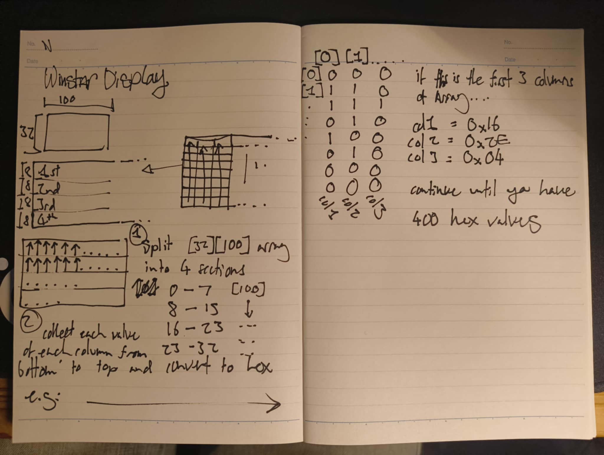
I don't want to calculate 400 hex values by hand
Next was to write a small Python program that took an appropriately sized PNG, and returned a text file with a formatted array, ready to be copied to my Arduino code, to do this I:
- Used Image from Pillow, to open and convert my .png from 32-bit RGBA (Aseprite default) to 8-bit grayscale.
- Extracted the pixel data into a list and then into an array using numpy.array().
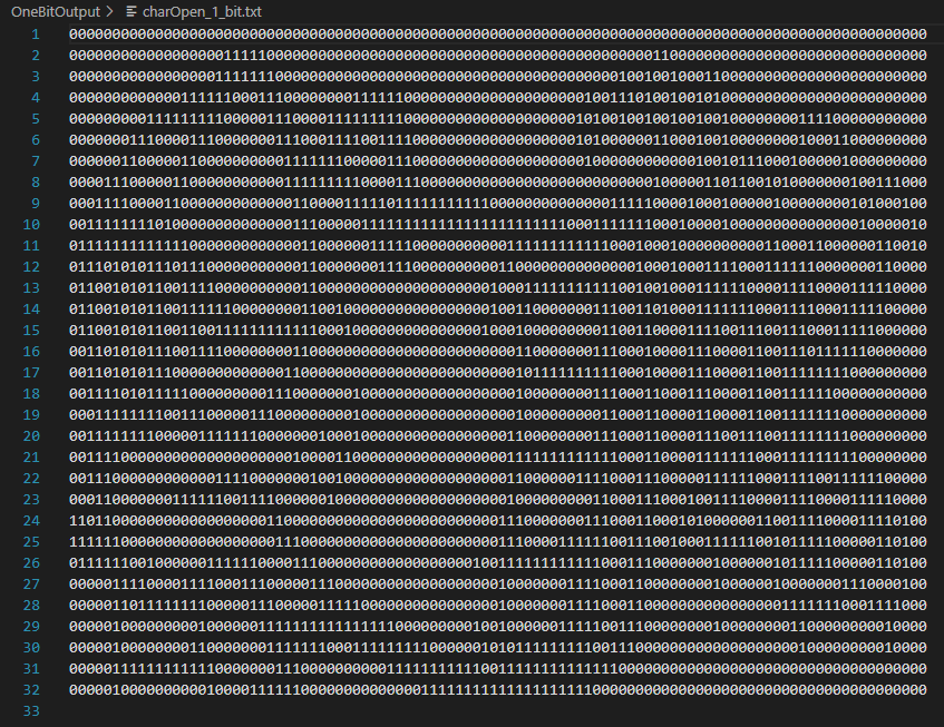
- convert each array value (currently an 8-bit value) to 1-bit based on a threshold value of 127, set each value to a 0 or 1.
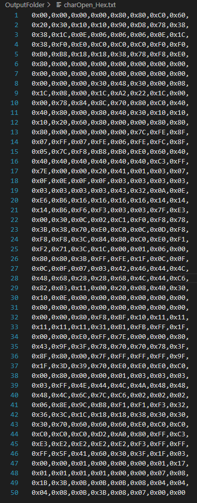
- Looped through the array, collecting 8 bits at a time, converting them to hexadecimal, and saving the result in an output file (output is formatted so it can simply be copy-pasted directly into my code).
Note that this has been specifically made for my Show_Pic function, there is a Github link at the top of the page.
Python Converter Code
    import sys
    from PIL import Image
    import numpy as np
    from pathlib import Path

    def ImageToByteArray(image_path):
        try:
            img = Image.open(image_path).convert("L")
            width, height = img.size
            pixel_data = list(img.getdata())
            bit_array = np.array(pixel_data)
            bit_array = 1 - ((bit_array > 127).astype(int))
            bit_array = bit_array.reshape((height, width))
            return bit_array
        except FileNotFoundError:
            print(f"Error: image file was not found at {image_path}")
            return None
        except Exception as e:
            print(f"Error: {e}")
            return None

    imageName = sys.argv[1]
    image_path = Path(Rf"InputFolder\{imageName}.png")
    bit_array = ImageToByteArray(image_path)

    if bit_array is not None:
        np.savetxt(Rf"OneBitOutput\{imageName}_1_bit.txt", bit_array, fmt="%d", delimiter="")
        valCounter = 0
        hexBox = []
        for z in range(4):

            for i in range(100):
                binaryString = ""
                binaryInt = 0

                for j in range(8):
                    bit = str(bit_array[j + (z*8)][i])
                    binaryString += bit

                binaryString = binaryString[::-1]
                intVal = int(binaryString, 2)
                hexVal = f"0x{intVal:02x}"
                hexBox.append(hexVal)

        hexBox = ["0x" + val[2:].upper() for val in hexBox]

    with open(Rf"OutputFolder\{imageName}_Hex.txt", "w") as f:
        for i in range(0, len(hexBox), 8):
            line_items = hexBox[i:i+8]
            line = ",".join(line_items)

            is_last_line = (i + 8 >= len(hexBox))

            if is_last_line:
                f.write(line)
            else:
                f.write(line + ",\n")
Formatted hex output
Fun visualisation of the converted 1-bit image

From a single .ino file to a valid Arduino library and low-level driver
At this point I had never contributed to an open source project or published some code/program that may be useful to others, I had always wanted to but I just didn't know what to do. After reflecting on my struggles and progress while getting this display to work, it jumped out as the perfect project to share online! The next step was to create a device driver and Arduino library that others could use, along with documentation and supplementary material such as my Python image converter. The driver would serve as a reference for people working with dual WS0010/S0010 chip displays, plus hopefully be fully functional for anyone with my model or a slight variant of it.
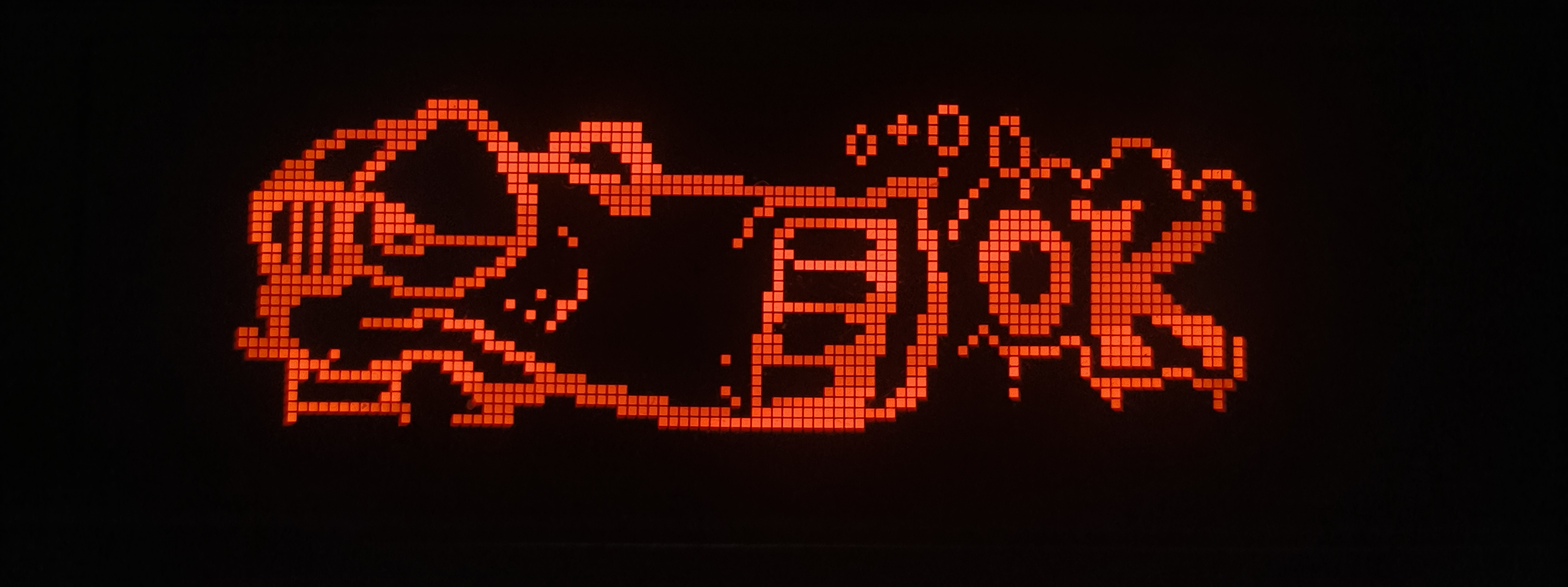
After looking at drivers and Arduino libraries that others had created, I began to build mine. The first issue I had was figuring out how to test what I had written on my OLED display. Currently I had all my code in a single .ino file, but this would need to be split up into my WS0010_WEG010032.cpp, WS0010_WEG010032.h and main.cpp files. Reddit recommended me to check out PlatformIO's extension for VSCode, this was perfect as it allowed me to build and upload my Arduino sketch in its new file structure, without using the official Arduino IDE. My header file declares the WS0010_Display class and associated functions, as well as macros for common instruction values. This was also the first time I'd have public: and private: declarations in a header file, also using an appropriate underscore prefix to help differentiate public and private declarations. My main WS0010_WEG010032.cpp file contains public functions such as a contructor, initialisation, displaying an image and clearing the display, in the future I'd like to create some new functions to allow geometry drawing similar the the Adafruit_GFX library. There is also sample code which is what I currently have running on my display, the image is of "Screws", a character created by Vaughn Bode.
If you would like to use the library for yourself, all you need to do is:
- Download the repository as a .ZIP.
- In a new Arduino sketch, navigate to 'Sketch' -> 'Include Library' -> 'Add .ZIP Library...'
- Make sure to then include the header file with
#include <WS0010_WEG010032.h>at the beginning of your code. - You can now access all public functions!
- If you want to see an example, there is an example.ino sketch as well as a photograph of my wiring between the Arduino and display.
Display in the dark
Making it faster
As a bonus, here is the same animation with delay() calls removed from the main Loop(). It looks so much better than one of the standard LCD screens people buy for microcontroller projects, the datasheet states the system cycle time is 500ns (along with other timing requirements I dont fully understand yet), this cycle time means that the display could hit a very theoretical framerate of 5000fps as each byte takes 500ns, with 400 bytes per frame it would take 0.2ms each, therefor 1s/0.0002s = 5000fps. This is very simplified though, and im not exactly sure how much I can personally push it, especially with my Arduino Uno.
Plans for the future
I will continue to add new functions to my driver and library, as well as adjust the code so it is more stable and quicker, I know that some of the delay() calls could be smaller, and I still need to fix the _checkBusy() function and its implementation because I don't really trust it right now. At the time of writing, I'm using this display on a breadboard with jumper wires on an Arduino Uno. I have bigger plans to use a Raspberry Pi Pico 2 and a NOR Flash Module, utilising the Pico's higher clock speed, direct memory access, 12 PIO state machines, and much more optimised code to push the refresh rate limit of the display, creating ultra smooth animations (and play Bad Apple!!). Hopefully this will have some sort of utility as well, I'm sure I'll think of something in the future.
Thanks for reading!!