Isolated Computer RGB!
I wanted to add customisable RGB lighting inside my PC case without relying on software running on my operating system to control it. Since building my PC, I have wrestled with different RGB lighting software to manage my CPU cooler and graphics card. None seemed reliable, as the RGB would often "reset" to factory settings, and I didn't like the idea of it constantly running in the background. The fact that I dual-boot also complicated things, as I needed a Linux-compatible alternative.
My solution was to control WS2812B LED strips using a microcontroller and power both the LEDs and the controller directly from my PC’s power supply. This ensures they automatically turn on and off with the PC.
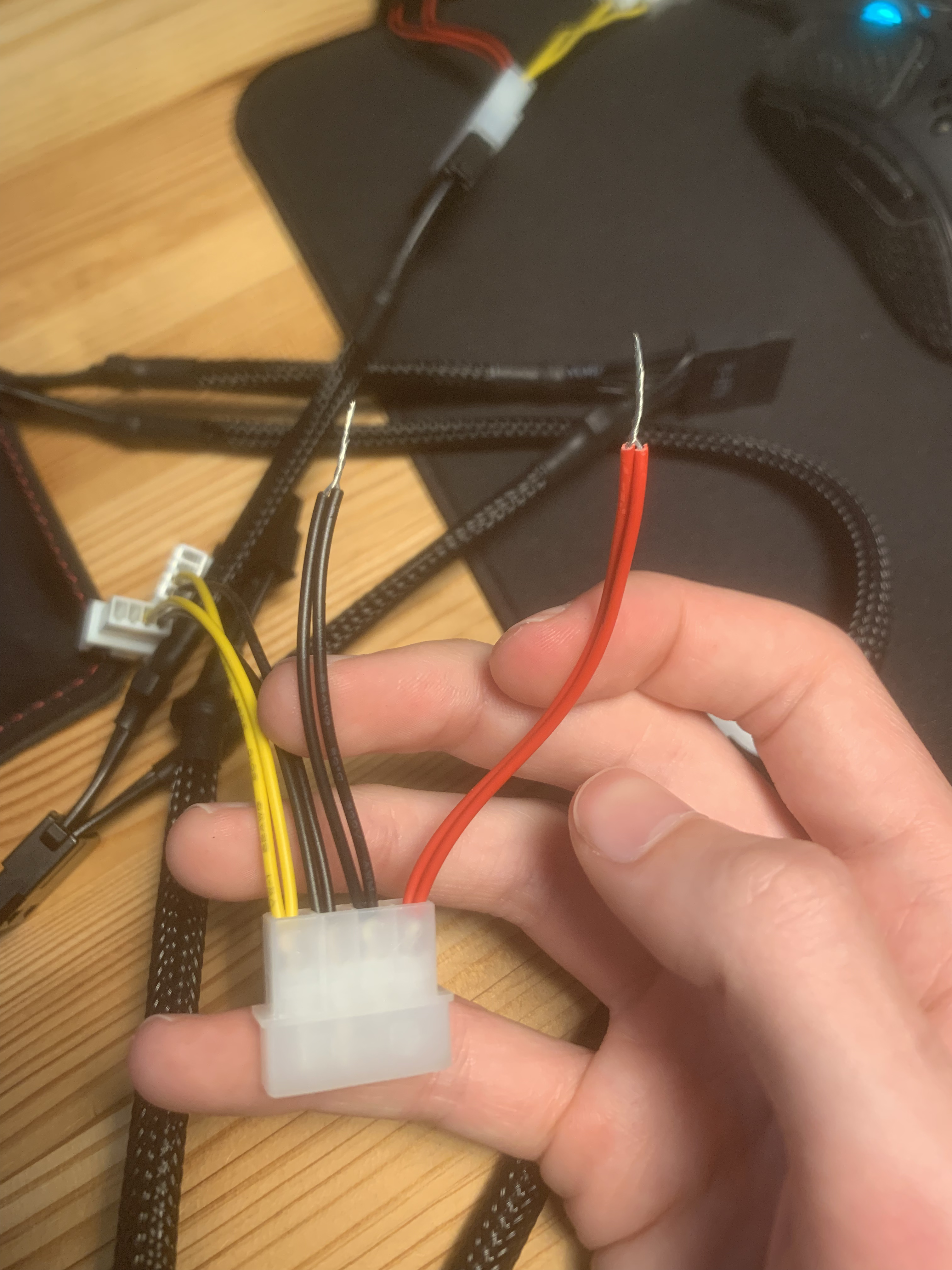
The power supply in my computer is rated at 25A on the 5V rail. I chose this because my Arduino Uno can be directly powered by it, as can the 5V LEDs. To access the 5V rail, I bought a Molex connector from AliExpress, cut off the connectors, and soldered both the red (5V) and black (ground) wires together. This setup is pretty janky, and upgrading it is my next priority.
Janky Molex
I purchased 2 metres of WS2812B LED strips along with curved silicone diffuser tubes to create a smoother lighting effect. My idea was to have multiple short LED strip runs extending from the corners of the PC case toward the CPU/GPU, making it look like "energy" was being pumped into the heart of the system.
I cut down the LED strips into lengths of around 28–33 LEDs. They didn’t all have to be exact—if there were fewer LEDs than the program expected, it would still send the data as if they were there, allowing all strips to run in sync.
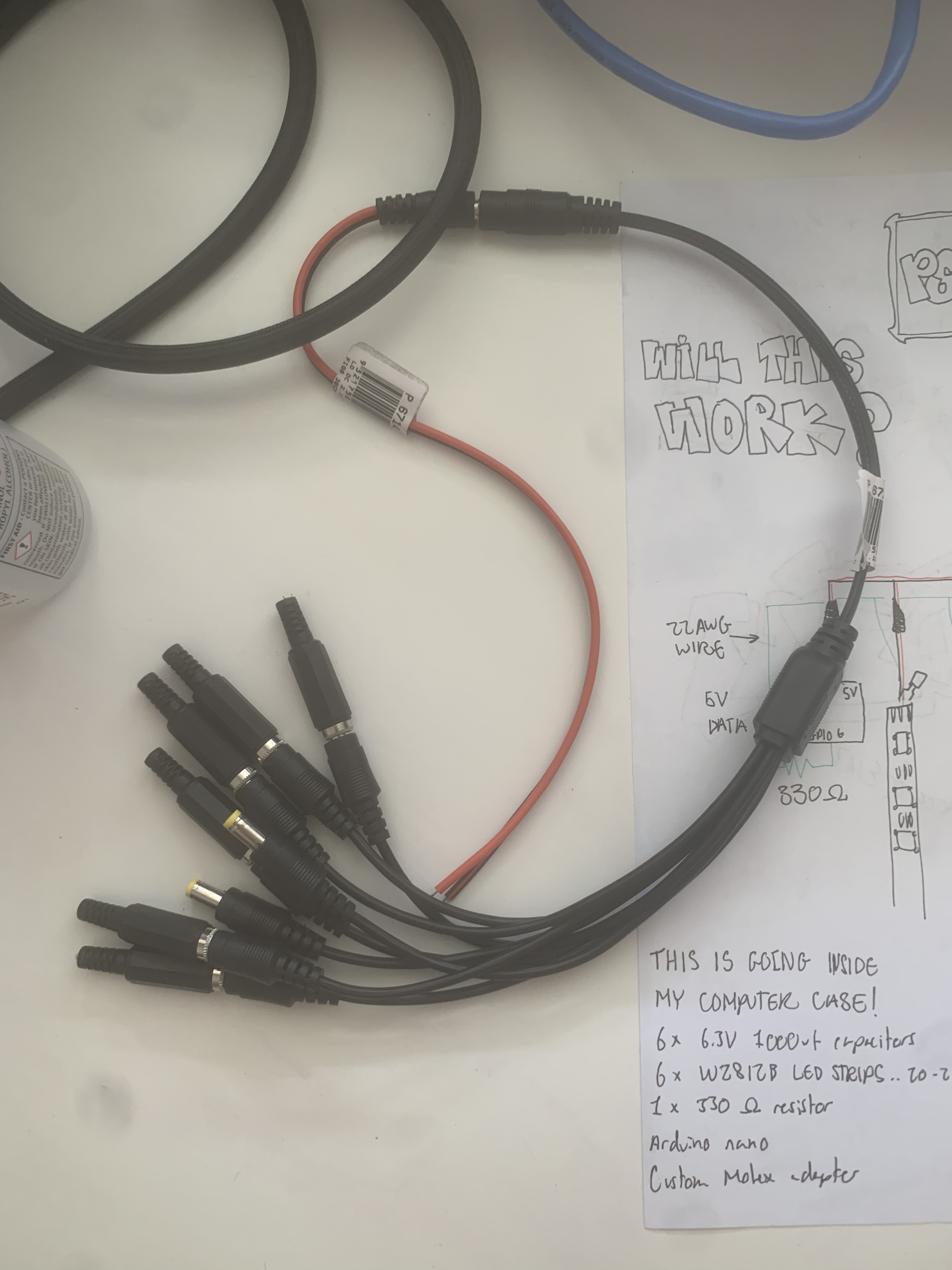
To distribute power to each LED strip and the Arduino, I bought a 1-to-6-way barrel jack splitter. This allows me to unplug any LED strip at any time if one gets damaged or if I want to remove it. It also gives me the flexibility to add more strips as long as I have available connections.
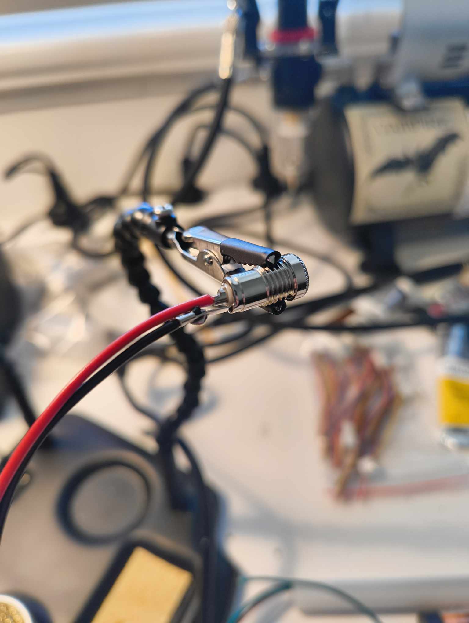
I soldered new power, ground, and data lines to each strip using 22 AWG wire, then soldered the power and ground wires into their respective female barrel jack connectors.
Click for some pics
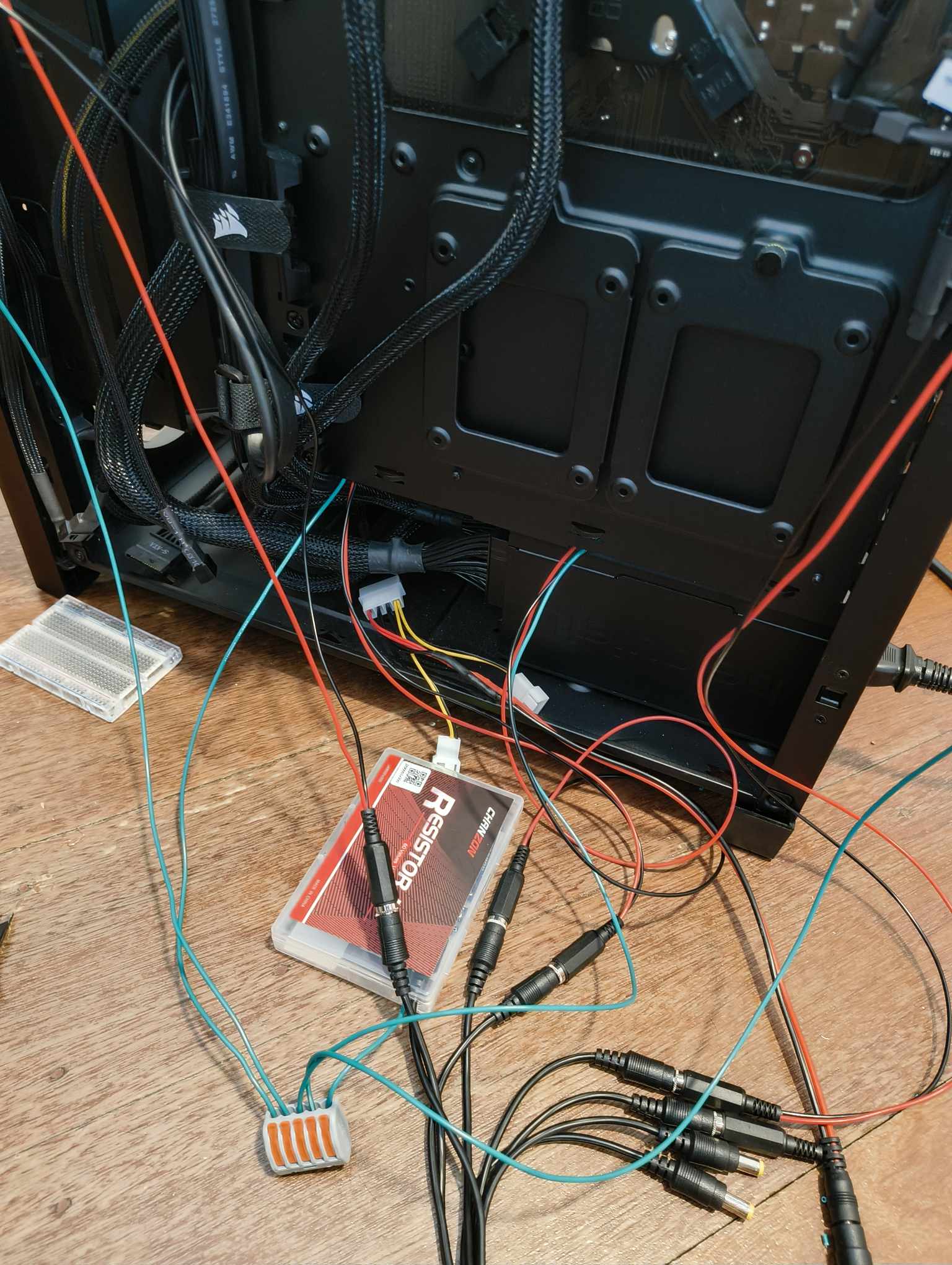
The splitter is wired to the Molex cable, ensuring power and ground are correctly matched.
Since my Arduino Uno has a barrel jack connector, it was easy to plug it directly into the 6-way splitter for power.
To connect the data lines together, I used a Wago 5-way connector. While it isn’t designed for permanent solutions, I decided it was suitable since it draws little current and remains stationary, reducing the risk of it being knocked or damaged. I connected each LED strip’s data line to the Wago connector, along with a wire that leads from the last remaining slot to a data pin on the Arduino.
I used the FastLED library to program the LEDs. This library runs efficiently on an Arduino and allows for the exact complexity of LED effects I was aiming for.
The code
#include <FastLED.h>

#define NUM_LEDS 33
#define DATA_PIN 6

CRGB leds[NUM_LEDS];

void setup() {
  FastLED.addLeds<WS2812B, DATA_PIN, GRB>(leds, NUM_LEDS);
  FastLED.setBrightness(200);
  fill_solid(leds, NUM_LEDS, CRGB::Black);
  FastLED.show();
}

void loop() {
  pumpEffect();
}

void pumpEffect() {
  for (int i = 0; i < NUM_LEDS; i++) {
    // Currently is pure red to pure blue blend.. mainly purple though
    leds[i] = blend(CRGB(255, 0, 0), CRGB(0, 0, 255), map(i, 0, NUM_LEDS - 1, 0, 255));

    // Leave fading trail behind focus led
    for (int j = 0; j < NUM_LEDS; j++) {
      leds[j].fadeToBlackBy(80);  // fade duration
    }

    FastLED.show();

    // note: Increase max delay for more dramatic ramp up
    // note: Increase exponent for more pronounced effect
    float delayFactor = pow((1.0f - ((float)i / (NUM_LEDS - 1))), 4.5);
    int delayTime = 2 + (120 * delayFactor);

    delay(delayTime);
  }
}
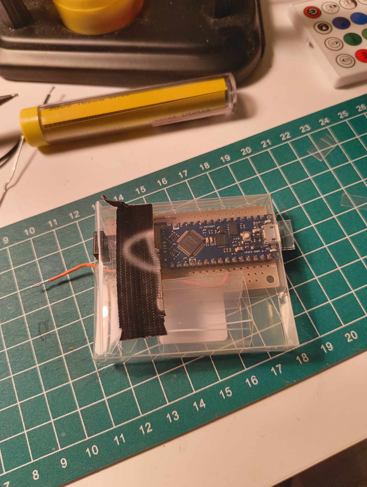
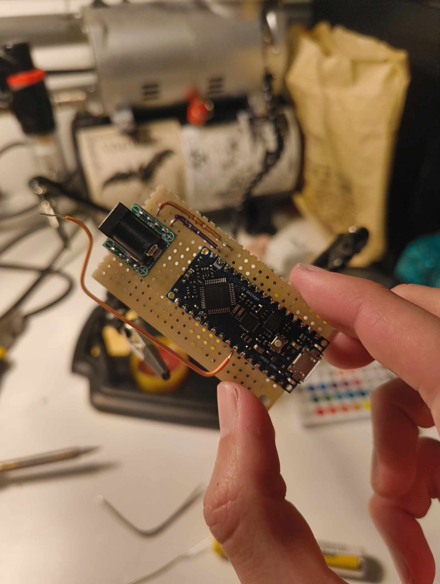
Eventually, I decided I wanted my Arduino Uno back, so I purchased an Arduino Nano instead. The Nano is smaller, has a faster clock speed (20MHz vs 16MHz), and still uses 5V logic levels. I soldered the pins onto the Nano and mounted it on a piece of protoboard along with a barrel jack for power and a wire for the data line.
For housing, I repurposed an old plastic container, cutting it to fit the components inside. It doesn’t look the best, but it provides access to the USB port on the Nano as well as the data line and jack connector.
Nano pics + running vid